OpenCV Camera Calibration with Python: A Robust Workflow for Industrial Machine Vision
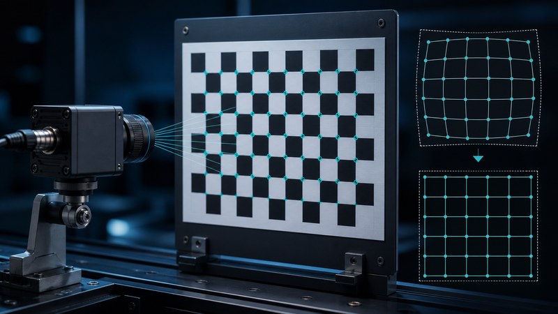
In short: camera calibration estimates a mathematical model of a camera. From known points on a calibration target and their positions in the image, OpenCV calculates the camera matrix and distortion coefficients, among other parameters. These results can be used to correct lens distortion, describe image rays geometrically and – with suitable measurement geometry – relate pixel observations to real-world coordinates.
For industrial applications, however, it is not enough for cv.calibrateCamera() to finish without an error. Quality depends on the target, image coverage, viewing angles, focus, resolution and mechanical stability. A low mean reprojection error is useful evidence, but it is not proof of measurement capability and not a release for production use.
What does camera calibration estimate?
The common pinhole model separates intrinsic and extrinsic quantities. Intrinsic parameters describe image formation inside the camera: focal lengths in pixels, principal point and the selected coefficients for radial and tangential distortion. Extrinsic parameters describe the pose of the calibration target relative to the camera for each captured view.
OpenCV therefore needs corresponding points: known object points on the target and the detected image points. For a planar checkerboard, the object points lie in one plane. If the real square size is known and entered correctly, the resulting translation values use the same unit. That fact alone does not turn the camera into a traceable measurement system.
When is calibration required?
- when distortion affects geometric evaluation, dimensional inspection or overlays,
- when image points need to be transformed into a world, robot or component coordinate system,
- for stereo and multi-camera systems, where the relative camera poses must also be determined,
- when estimating pose from known 3D points with
solvePnP(), - and whenever a change to the lens, focus, resolution, crop or mechanics alters the imaging geometry.
Pure classification tasks may not require geometric calibration. That decision should follow from the inspection task, not from a desire to avoid the additional work.
An eight-step robust workflow
- Fix the acquisition state: document the camera, lens, focus, aperture, resolution, binning, crop and relevant mechanical positions. The calibration belongs to this exact configuration.
- Use a suitable target: a planar checkerboard, circle grid or ChArUco board must be rigid, high-contrast and dimensionally known. For an OpenCV checkerboard, pattern size means the number of inner corners, not the number of squares.
- Capture diverse views: place the target across the complete field of view, include the edges and vary position as well as tilt. Many nearly identical images add little information and can leave the problem poorly conditioned.
- Inspect image points: detect checkerboard corners with
findChessboardCorners()and refine them withcornerSubPix(). Keep only completely and plausibly detected views. ChArUco can cope with partial occlusion and is designed for precise corner localisation. - Match object and image points: the order of detected corners must match the object-point order. An incorrect square size scales the extrinsic translation values incorrectly.
- Estimate parameters:
calibrateCamera()returns the camera matrix, distortion parameters, rotation vectors and translation vectors.calibrateCameraExtended()also returns estimated standard deviations and per-view reprojection errors. - Analyse error patterns: do not rely on the global RMS value alone. Per-view outliers, systematic residuals near the edges, implausible parameters and stability under slightly changed image sets are equally important.
- Validate independently: test the final calibration on images and references that were not used to estimate the parameters. Acceptance limits must come from the downstream measurement or inspection task.
The OpenCV Python tutorial names at least ten well-detected views as a starting point. This number is not a quality certificate. Ten diverse views with good field coverage can contain more useful information than fifty nearly identical images.
How to interpret reprojection error
During reprojection, the known object points are projected back into the image using the estimated parameters. Their distance from the actually detected corners describes how well the model explains the calibration data. OpenCV provides a global result and, through the extended function, errors for individual views.
A low value can still be misleading. The model may explain the captured images well while failing in poorly covered edge regions. A warped printed target, incorrect dimensions or an unstable optical setup can also produce numerically calm results that do not match the later measurement task. Error maps, visual inspection of straight structures and independent reference measurements therefore belong in the assessment.
Correcting distortion: account for image content and validity
OpenCV provides undistort() as well as precomputed maps using initUndistortRectifyMap() and remap(). In getOptimalNewCameraMatrix(), the alpha parameter controls the compromise between a fully valid image region and retained field of view: a stronger crop leaves fewer invalid pixels, while keeping more of the original view can introduce black borders.
This step changes the usable image area. Regions of interest, coordinate transforms and downstream algorithms must therefore use the same corrected image geometry. Store the camera matrix and distortion parameters together with resolution, configuration, OpenCV version, date and validation status.
Common mistakes in practical projects
- Counting squares instead of inner corners: a board with 10 × 7 squares has 9 × 6 inner corners.
- Showing only the image centre: the more strongly distorted edge regions then remain poorly constrained.
- Collecting similar poses: repeated front-facing views do not replace variation in tilt, position and distance.
- Bending the target: a wavy sheet violates the assumption of known planar geometry.
- Resizing or cropping later: the camera matrix does not remain directly valid for a different image geometry.
- Reporting only the mean: individual poor views and local residuals remain hidden.
- Confusing calibration with approval: without reference artefacts, an error budget and repeatability testing, essential evidence for industrial use is still missing.
What industrial validation still requires
A mathematically plausible calibration is only one part of the measurement chain. Real deployment also requires consideration of mechanical repeatability, temperature, working distance, depth of field, illumination, reference quality and the permissible error of the inspection task. Validation uses the intended system, real images and defined criteria.
This is where traceable documentation becomes valuable: which file belongs to which camera-lens configuration? Which views were excluded, and why? Which limits apply? Which reference confirms the usable range? These relationships can also be represented in a knowledge graph for industrial machine vision.
Conclusion
Good OpenCV camera calibration begins before the function call, with stable acquisition geometry and a useful dataset. Evaluating field coverage, pose diversity, per-view errors and independent references produces more than a parameter file: it produces a calibration with a traceable range of validity.
For industrial machine vision, the sequence is therefore clear: estimate parameters, inspect the result visually, measure independently and version the complete configuration. Only this chain makes the result technically robust.